

A Houdini Engine tool that isolates and fractures only the section of geometry intersected by the animated object, then stitches the fractured section back into the original geometry.
This Houdini HDA takes two Unreal Engine meshes as inputs: a target mesh to be fractured and an animated impact mesh. The HDA uses the motion of the impact mesh to procedurally define the fracture region and generate impact points on the target. Parameters exposed in Unreal allow artists to art-direct the impact, including the size, density, and distribution of the resulting fracture and simulation.
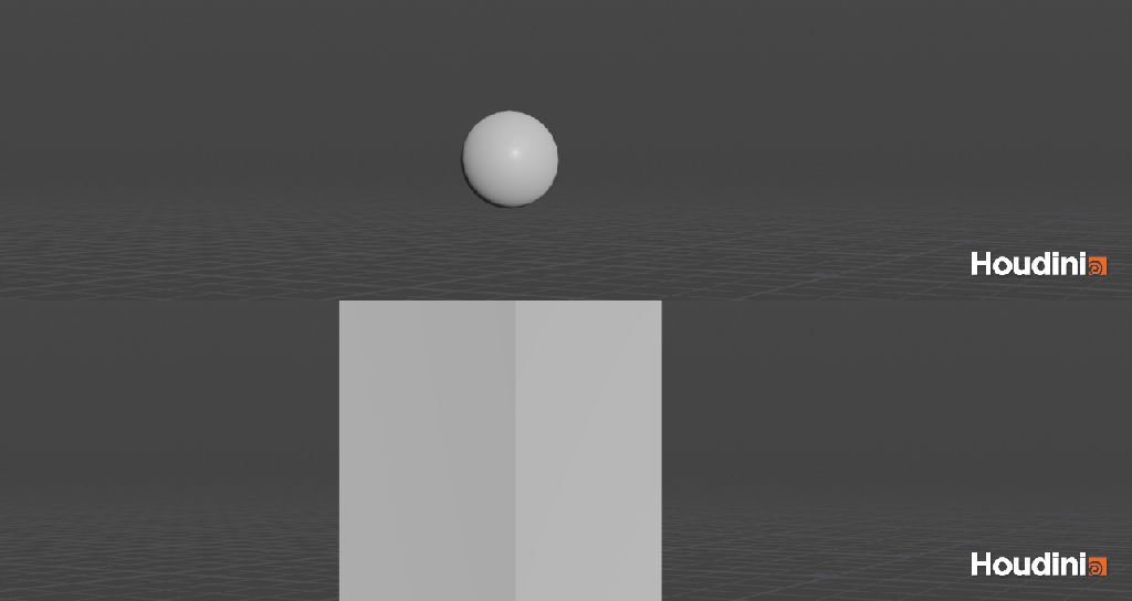
To demonstrate the principle, the example uses two simple objects: a sphere, which represents the animated impact object, and a pillar, which represents the object being fractured.
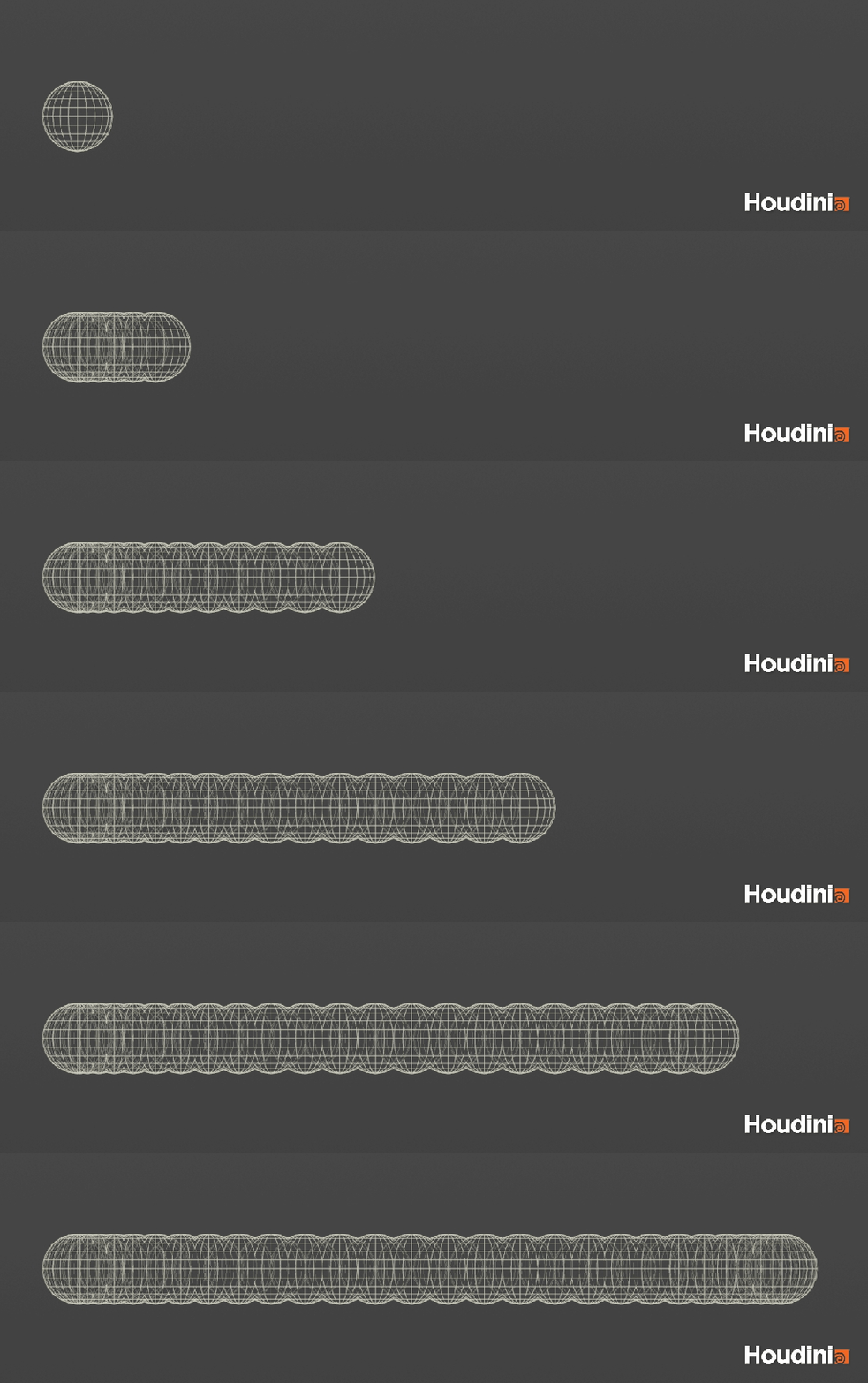
First, we trail the animated impact object—in this case, the sphere. The trail captures the sphere’s motion over time, creating a representation of the path it travels through the scene.

We then extract the centroid of the trail object. This gives us a series of points representing the path of the animation over time. These points define the impact trajectory and are used to build the bounding volume around the sphere’s motion.
We then use a Time Shift to move the animation to its final frame. This freezes the animated impact object at the end of its motion while preserving the complete trajectory captured by the trail. This gives us a static representation of the impact path that can be used for the subsequent bounding and Boolean operations.
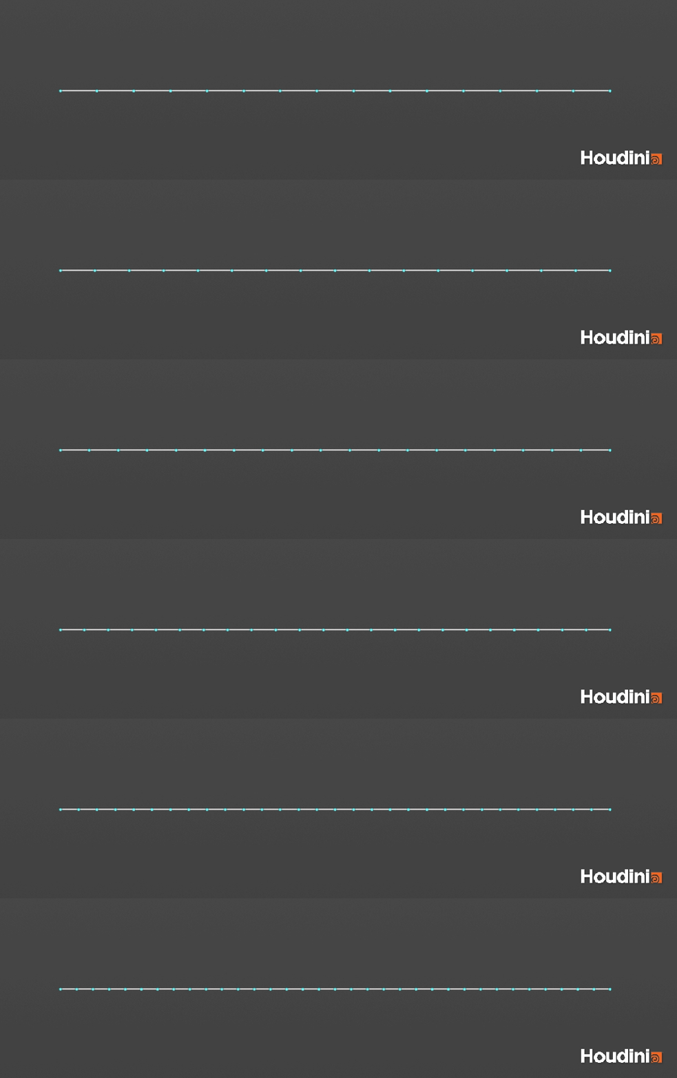
Next, we connect the centroid points by creating a line along the sphere’s trajectory. We then resample the line to control the number of points along the path. Increasing the resample density adds more detail to the resulting mesh, allowing the user to better capture complex or fast-moving animations. The appropriate resample value will depend on the complexity and speed of the impact motion.
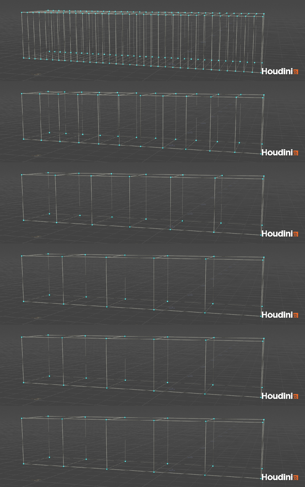
Next, we copy planes onto the resampled points along the trajectory. The planes should be sized to match the impact object, with additional padding to give the user control over the size of the affected area. We then skin/sweep these planes to create a continuous bounding volume that encompasses the entire path of the animated object. This volume will be used to define the area of the pillar affected by the impact.
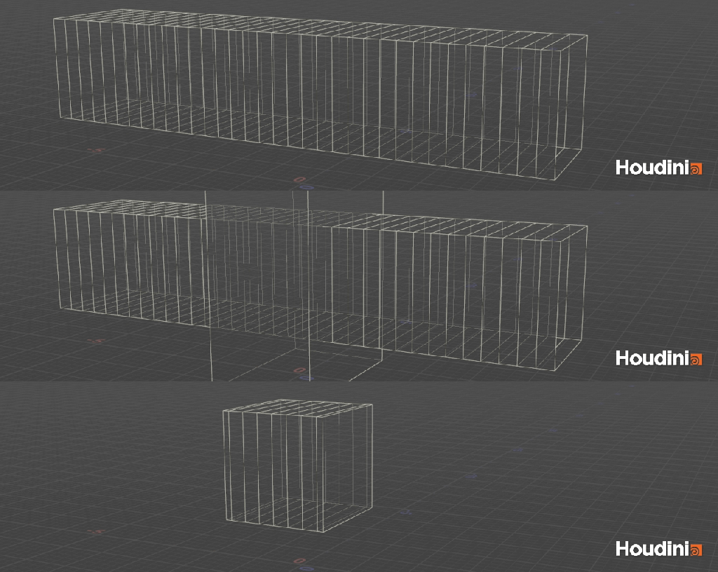
We then take the bounding object and Boolean it with the pillar. This creates a localized fracture patch around the path of the impact. The patch isolates the area of the pillar that will be fractured later in the process, allowing the rest of the pillar to remain unaffected.
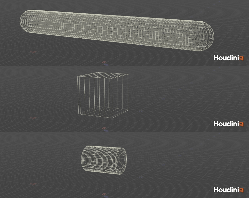
We now need to create two bounding volumes that will be used to generate the impact points. The first bounding volume is created by taking the original trail volume and Booleaning it with the fracture patch. This defines the inside group, representing the area directly affected by the moving impact object.
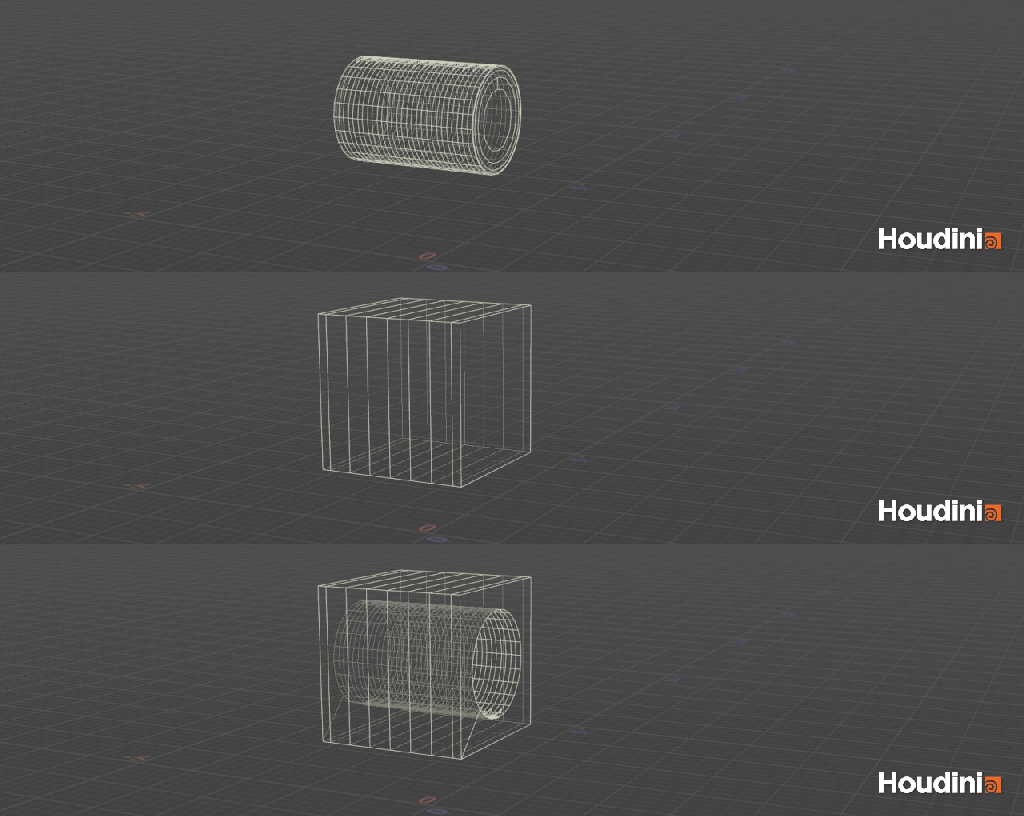
The second bounding volume is created by subtracting the inside region from the fracture patch. This gives us the outside group, representing the remaining area of the fracture patch surrounding the direct impact region.
These two volumes will allow us to control the distribution of impact points and later classify the fractured pieces based on their proximity to the impact.
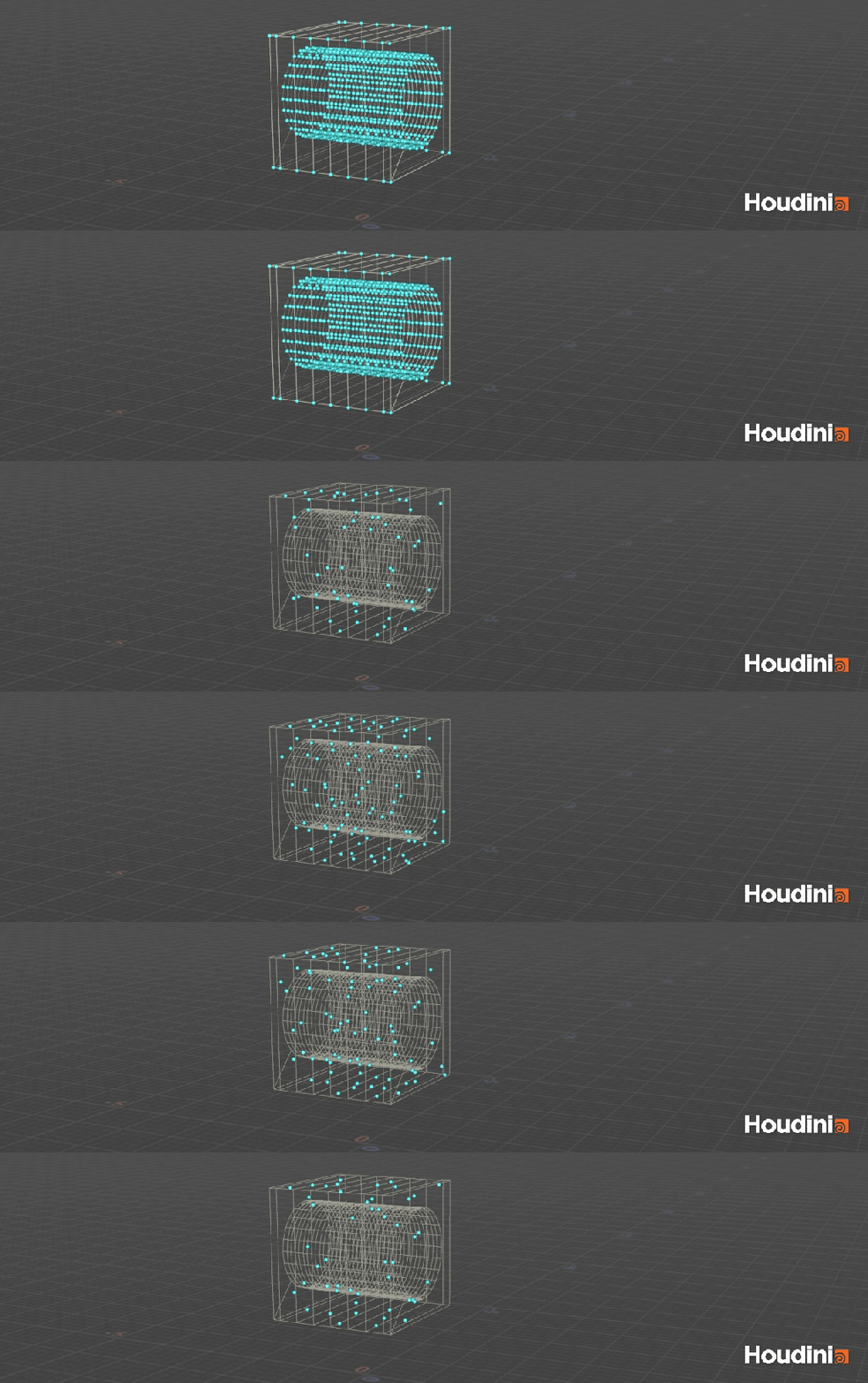
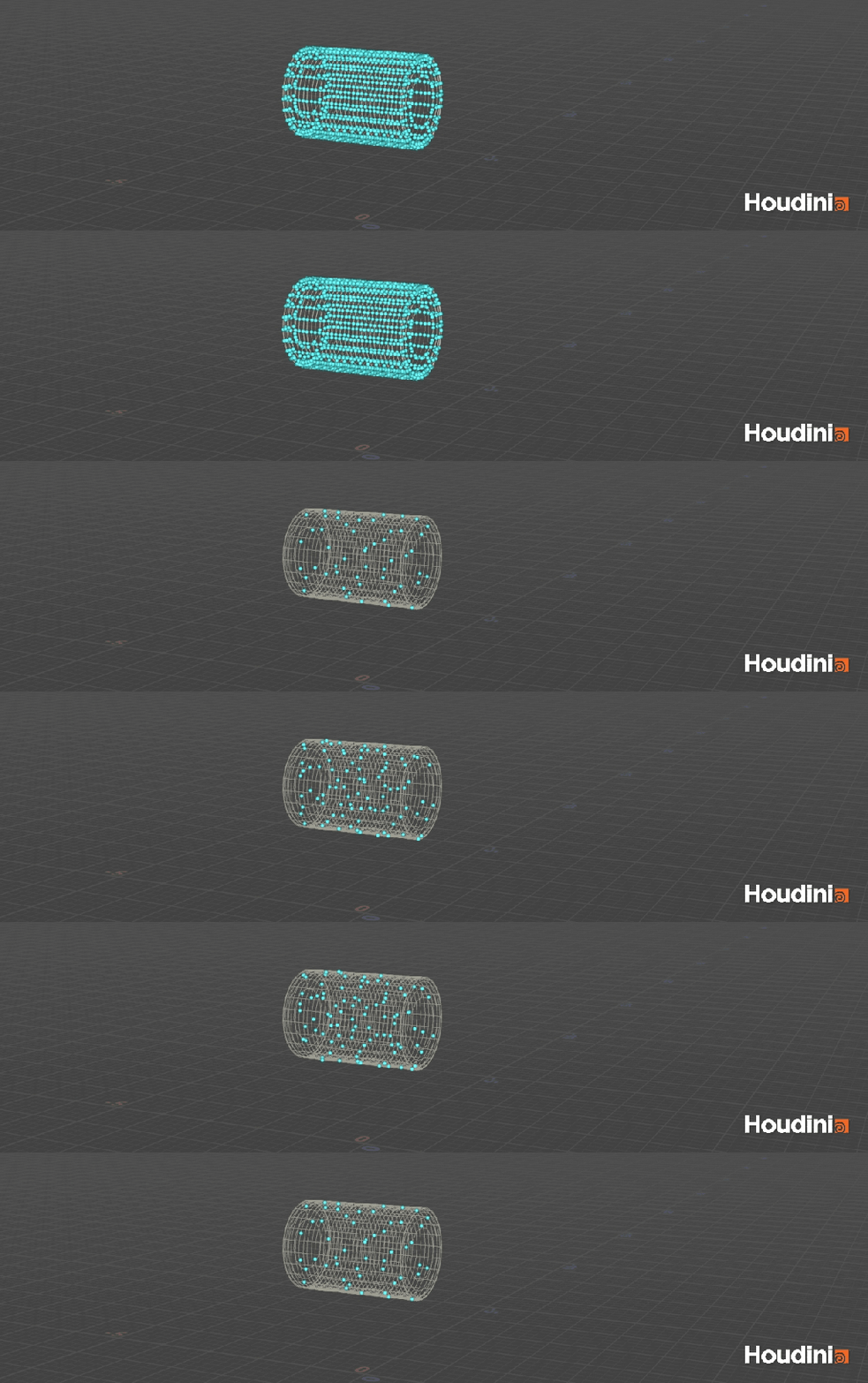
We can then scatter points within each of the two bounding volumes. The density of the scattered points can be adjusted to control the number and distribution of impact points within the inside and outside regions.
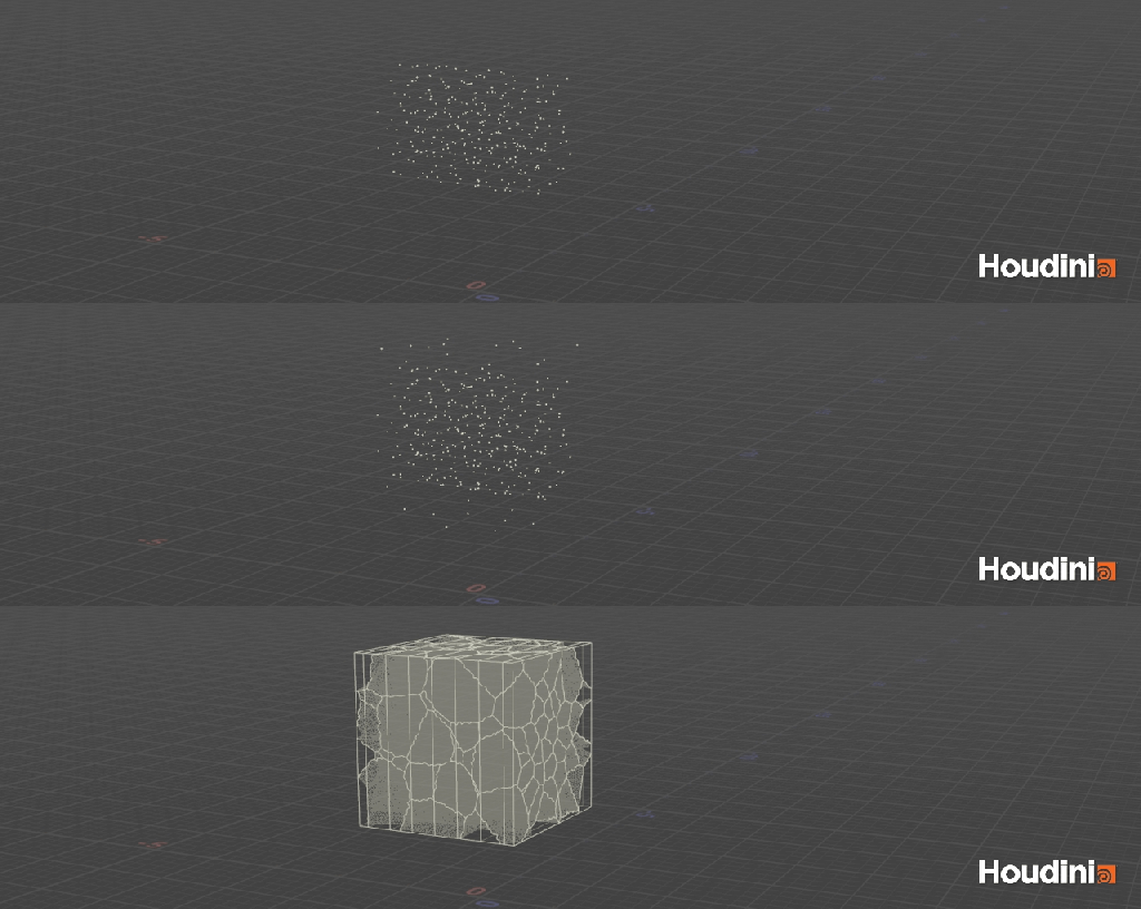
We then merge the points from both volumes to create a single set of impact points. These points are used to fracture the patch, creating the individual pieces that will later be assigned to the different simulation groups.
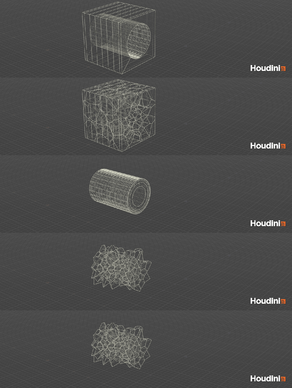
We then use the same bounding volumes created from the Boolean operations to classify the fractured pieces into inside and outside groups. This allows us to control the behavior of each group independently during the simulation.
For example, we can set the inside group to be active while keeping the outside group inactive. We can also use these groups to drive additional simulation properties such as sleep, pin, constraint strength, and other physical attributes.
This gives us a flexible way to control how the destruction propagates from the initial impact through the rest of the fractured object.
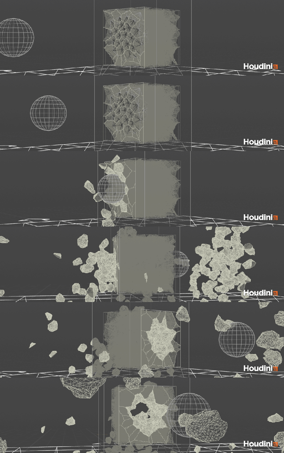
The final step is to take the fractured pieces and their constraints into the simulation. Once the simulation is complete, we add bones to the fractured pieces and bind them to the resulting motion. The simulated geometry can then be exported as a Skeletal Mesh for use in Unreal Engine.
Here is a more detailed breakdown of the tool.
